
Wireless-Charging Xbox Controller
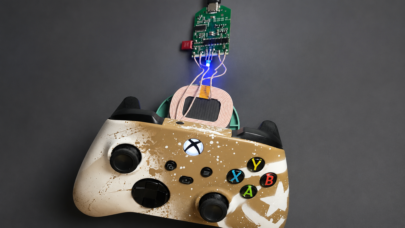
A controller is most useful when it is already charged and ready to use. In this project, I modified an Xbox Series X|S controller by installing a rechargeable lithium battery, a wireless-charging receiver, and a regulated 3-volt power supply inside the original housing.
The finished prototype powers the controller normally and begins charging when it is placed on a compatible wireless-charging pad. The current circuit uses separate boost and buck converters, proving the concept while leaving room for a more efficient future revision.
1. Project Goal
The goal was to replace disposable AA batteries with an internal rechargeable battery that can be charged without connecting a cable to the controller. When the controller is placed on a wireless-charging pad, the receiver coil transfers power to the charging circuit and recharges the internal battery.
2. Why the Controller Cannot Use the Battery Directly
A standard Xbox controller normally uses two AA batteries connected in series. With approximately 1.5 volts per cell, the controller receives around 3 volts.
A rechargeable single-cell lithium battery behaves differently. Its nominal voltage is approximately 3.7 volts, and a fully charged cell can reach approximately 4.2 volts. Connecting this voltage directly to the controller would exceed the normal AA-battery supply voltage.
| Power source | Typical voltage | Suitable for direct connection? |
|---|---|---|
| Two alkaline AA batteries | Approximately 3.0 V when new | Yes, this is the controller’s normal battery configuration. |
| Single-cell lithium battery | Approximately 3.0 V to 4.2 V | No. The voltage must be regulated before it reaches the controller. |
| Regulated converter output | Approximately 3.0 V | Yes, after polarity and voltage have been verified. |
3. Circuit Overview
The prototype contains two connected electrical paths. The charging path transfers energy from the wireless receiver to the battery. The power path converts the battery voltage into a stable supply for the controller.
4. Required Components
For the working prototype, I used the following components:
5. Testing the Wireless-Charging Circuit
Before modifying the controller, I tested the charging system separately. I connected the battery to the designated battery terminals of the charging receiver and placed the receiver coil on a wireless-charging pad.
The charging system activated and the battery began charging. Testing the circuit outside the controller made it easier to verify polarity, charging behavior, and component temperature before installation.
I currently use a standard wireless-charging pad. A future version could include a custom stand that holds the controller and aligns the coil automatically.
6. Creating a Stable 3-Volt Supply
The buck converters available for this prototype require an input voltage of at least approximately 4.5 volts. Because a single lithium cell only provides approximately 3 to 4.2 volts, the buck converter could not be connected directly to the battery.
I therefore used a boost converter to raise the battery voltage to 5 volts. A second converter then reduced this voltage to a stable 3 volts for the controller.
| Measurement point | Measured voltage | Purpose |
|---|---|---|
| Battery | Approximately 3.9 V during the test | Energy source for the complete circuit. |
| Boost-converter input | Approximately 3.9 V | Directly connected to the battery output. |
| Boost-converter output | Approximately 5.0 V | Provides sufficient input voltage for the buck converter. |
| Buck-converter output | Approximately 3.0 V | Regulated supply connected to the controller. |
7. Completing and Verifying the Circuit
After connecting the charging and power-conversion stages, I measured the voltage at every point in the circuit. The final output remained close to 3 volts, so the prototype was ready for installation.
I temporarily disconnected the boards again because the final component positions and cable lengths depended on the available space inside the controller.
8. Disassembling the Controller
I first removed the side grips using a plastic opening tool. The battery-compartment sticker hides one of the housing screws, so I removed the sticker and then loosened the hidden screw together with the four remaining screws.
After all five screws were removed, the two housing sections could be carefully separated. Opening the housing slowly reduces the risk of damaging clips, wires, buttons, or internal components.
9. Modifying the Battery Compartment
The original AA-battery structure occupied too much space for the rechargeable battery and converter boards. I used a small rotary-tool saw to remove the internal section of the battery compartment.
I removed only the material required for the electronics and kept the mounting features used by the original battery cover. This allows the cover to remain securely attached after the modification.
10. Preparing the Wireless-Charging Receiver
I added pin headers to the receiver board and installed a removable connector in the battery wiring. The charging coil remains attached to the battery cover, while the connector allows the cover to be separated from the controller during maintenance.
This arrangement prevents the coil wires from pulling directly on small solder joints whenever the battery cover is removed.
11. Connecting the Controller
I soldered two wires to the controller’s battery power terminals and connected them to the regulated 3-volt output of the DC-DC circuit. The polarity was checked before soldering and verified again before the controller was powered.
The wires were routed away from buttons, screw posts, trigger mechanisms, and housing edges. Exposed solder joints were insulated to prevent accidental contact with the circuit boards or shielding.
12. Installing the Electronics
I secured the converter boards with double-sided tape and checked that they could not move when the controller was handled. The battery was placed inside the modified compartment and connected to the converter input.
The wireless-charging receiver and coil were then connected to the battery. Before closing the housing, I confirmed that no wires were pinched and that the buttons, triggers, and battery cover still moved correctly.
13. Final Test
The controller powers on normally and connects to the Xbox without any problems. When it is placed on the wireless-charging pad, the receiver activates and the internal battery begins charging.
The prototype successfully demonstrates the concept: the original controller can be powered from an internal rechargeable battery and recharged wirelessly without modifying its external charging port.
The main improvement for a future version would be replacing the separate boost and buck converters with one efficient buck-boost converter. A purpose-built charging stand could also improve coil alignment and make the controller easier to place correctly.
Completed prototype charging on a compatible wireless-charging pad.
14. Current Limitations and Future Improvements
15. Frequently Asked Questions
Why not connect the lithium battery directly to the controller?
A fully charged single-cell lithium battery can reach approximately 4.2 volts, while the controller is designed around a supply of roughly 3 volts from two AA batteries. A regulated converter keeps the controller supply within the intended range.
Why does the prototype use both a boost and a buck converter?
The available buck converter required a higher input voltage than the battery could provide. The boost converter first raises the voltage to 5 volts, and the buck converter then reduces it to 3 volts. This works for testing but is less efficient than a suitable buck-boost converter.
Does every wireless-charging receiver safely charge a lithium battery?
No. Some receivers only provide a regulated output, commonly 5 volts. A lithium battery requires a dedicated charging circuit with the correct constant-current/constant-voltage charging profile, termination behavior, and protection.
Why is undervoltage protection necessary?
If the controller continues drawing current after the battery reaches its safe minimum voltage, the cell can be over-discharged and permanently damaged. A protected cell, protection board, or converter with low-voltage shutdown prevents this.
Can the original battery cover still be removed?
Yes. The charging coil is attached to the cover and connected through a removable plug. This allows the cover to be detached without pulling on the receiver-board solder joints.
Final Thoughts
This project shows how wireless charging, lithium-battery management, voltage conversion, and mechanical modification can be combined in one compact build. The prototype works, but battery safety and power-conversion efficiency are more important than simply fitting the components into the housing.
A future revision with a low-loss buck-boost converter, integrated protection, and a custom charging stand would make the modification cleaner and more practical for everyday use.