
Electronics Lab Tools
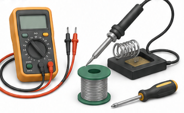
Learn how to use common lab tools such as a digital multimeter, bench power supply, oscilloscope, and basic measurement accessories.
1. What you will learn
2. Measurement reminders
3. Learning modules
Work through these modules in order. Each one builds an important practical skill for testing, powering, and debugging real electronics projects.
1 Multimeter basics Learn how to use the correct jack, mode, and range before connecting the meter to a circuit.
A digital multimeter is usually the first tool you use when checking a circuit. It can measure voltage, resistance, continuity, diode forward voltage, and current. Before every measurement, check two things: the selected mode on the dial and the socket where the red probe is plugged in.
For most measurements, the black probe goes into COM and the red probe goes into the V/Ω socket. Only move the red probe to the current socket when you really want to measure current. Leaving the probe in the current socket and then trying to measure voltage can short the circuit.
- Voltage: Used to check supply rails, batteries, sensor outputs, and logic levels.
- Resistance: Used to identify resistor values or check if a part is open or shorted.
- Continuity: Used to find broken wires, wrong solder joints, and connected pins.
- Diode mode: Useful for LEDs, protection diodes, and checking PN junctions.
- Current: Used to measure how much power a circuit actually consumes.
A good habit is to start with the highest safe range if your meter is not auto-ranging. Then reduce the range until the reading becomes stable and precise.
2 Safe voltage measurement Measure voltage in parallel and select AC or DC mode depending on the signal.
Voltage is measured between two points. This means the multimeter is connected in parallel with the part of the circuit you want to check. For example, to measure a 5 V rail, place the black probe on ground and the red probe on the 5 V point.
Use DC voltage mode for batteries, USB power, microcontrollers, sensors, and most low-voltage electronics. Use AC voltage mode for mains voltage or transformer outputs. Never guess when working with high voltage.
- Check polarity: A negative value usually means the probes are reversed.
- Use ground as reference: Most circuit measurements are taken between a signal and GND.
- Compare expected vs measured: A 5 V rail should be close to 5 V, not 3.2 V or 0 V.
- Measure under load: A supply can look correct with no load but drop when the circuit starts working.
Practical example: If an ESP32 project does not start, first measure the input voltage, then the 5 V rail, then the 3.3 V rail. This quickly tells you if the problem is power-related or somewhere else.
3 Current measurement Break the circuit and insert the meter in series only when the meter is configured correctly.
Current measurement is different from voltage measurement. To measure current, the meter must become part of the circuit. That means you have to break the circuit and insert the meter in series with the load.
This is one of the easiest measurements to get wrong. The meter has a very low internal resistance in current mode. If you place it directly across a power supply, it can create a short circuit and blow the meter fuse or damage the circuit.
- Move the red probe: Use the correct current input socket before measuring current.
- Start high: Begin with the highest current range, then move lower if needed.
- Measure in series: The current must flow through the meter.
- Check the fuse: If current mode always reads zero, the internal fuse may be blown.
For small electronics projects, current measurement is useful to check standby current, battery lifetime, LED current, motor load, and whether a module consumes more current than expected.
4 Bench supply setup Set voltage and current limit before connecting the circuit.
A bench power supply is one of the safest ways to power prototypes because it lets you control both voltage and maximum current. The voltage setting defines what the circuit receives. The current limit defines how much current the supply is allowed to deliver if something goes wrong.
Before connecting a circuit, set the correct voltage first. Then set a reasonable current limit. For example, if a small microcontroller circuit normally needs around 100 mA, you might start with a limit of 200 mA to 300 mA. If the circuit has a short, the supply enters current limiting instead of delivering unlimited current.
- CV mode: Constant voltage mode. The supply provides the selected voltage.
- CC mode: Constant current mode. The current limit is active, often because the circuit draws too much current.
- Current limit: A safety setting, not the current forced into the circuit.
- Polarity: Always check plus and minus before switching the output on.
A useful startup method is: set voltage, set current limit, connect the circuit, switch on the output, and watch the current display. If the current instantly jumps to the limit, switch off and inspect the circuit before continuing.
5 Oscilloscope basics Understand trigger, timebase, voltage scale, probe attenuation, and ground clip.
An oscilloscope shows how a signal changes over time. This makes it much more useful than a multimeter when checking PWM signals, clock signals, ripple, noise, startup behavior, button bouncing, or digital communication.
Start with the basics: connect the probe ground clip to circuit ground, place the probe tip on the signal, set a suitable voltage scale, and adjust the timebase until the waveform is visible. Then use the trigger to make the waveform stable on the screen.
- Voltage scale: Controls how many volts each vertical division represents.
- Timebase: Controls how much time each horizontal division represents.
- Trigger: Stabilizes repeating signals so they do not move across the screen.
- Probe setting: Match the oscilloscope setting to the probe, for example 1x or 10x.
- Ground clip: Usually connected to circuit ground. Be careful with non-isolated or mains-powered circuits.
Practical example: To check an Arduino or ESP32 PWM output, connect the ground clip to GND and the probe tip to the PWM pin. The oscilloscope can show frequency, duty cycle, voltage level, and whether the signal is clean.
6 Debugging workflow Start with power and ground, then move to signals, communication, and firmware behavior.
Good debugging is systematic. Do not start by replacing parts or rewriting code. First prove that the basic electrical conditions are correct. Most beginner problems are caused by missing power, wrong ground connection, reversed polarity, loose wires, wrong pins, or incorrect assumptions about a signal.
- Step 1: Check visual problems such as wrong wiring, bad solder joints, reversed connectors, and damaged parts.
- Step 2: Measure the supply voltage and confirm that the circuit has a stable ground reference.
- Step 3: Check whether the expected signal exists at the output pin, connector, or module input.
- Step 4: Use continuity mode to confirm that the signal really reaches the correct pin.
- Step 5: Use an oscilloscope or logic analyzer when the signal changes too fast for a multimeter.
- Step 6: Change only one thing at a time and test again.
A strong debugging rule is: measure the problem as close as possible to the source, then move step by step toward the load. For example, if an LED strip does not react, check the microcontroller pin first, then the cable, then the driver circuit, then the LED strip input.
4. Project connections
These examples show where the topic appears in practical ElektroBox builds.
5. Common mistakes
Skipping basic checks
Always verify power, ground, polarity, pin assignment, and the simplest possible test case first.
Changing too many things at once
Change one variable, test again, and document the result. This keeps debugging controlled.
Ignoring component limits
Check voltage, current, heat, pin limits, and power ratings before assuming a circuit is safe.
Final takeaway
Good measurement skills reduce guessing. Before replacing parts or rewriting code, measure what the circuit is actually doing.