
DIY Thermal Camera Sight
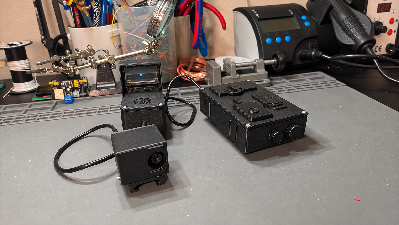
This DIY thermal sight combines an ESP32-WROOM, an MLX90640 thermal camera, and a 1.51-inch transparent OLED. The camera measures temperatures across a 32 × 24 grid, and the ESP32 turns those 768 readings into a simple symbol on the see-through display. You can still see the scene through the OLED while the symbol shows how close a warm spot is to the center of the camera’s view.
Parts list
Affiliate disclosure. If you buy through a link marked as an affiliate link, ElektroBox may earn a commission at no extra cost to you.
Use the original ESP32 board with the GPIO mapping below.
Shop part at aliexpress(affiliate link)Choose the narrow-field-of-view version. The sensor reads a 32 × 24 temperature grid.
Shop part at aliexpress(affiliate link)SSD1309, 128 × 64, configured for 4-wire SPI.
A 5 V USB power bank powers the ESP32 development board.
Repurpose a four-conductor cable for the sensor and insulate the solder joints.
Fasten the printed enclosure sections.
Main housing, OLED frame, separate camera housing, and rail mount.
Build the prototype
Prepare the sensor cable
Strip a short length of the salvaged USB data cable and identify its four conductors with a continuity meter. Slide heat-shrink tubing onto each wire, then solder the conductors to VCC, GND, SDA, and SCL on the sensor breakout. Keep track of the assignments at both ends and shrink the tubing over the joints.
Fit the sensor into its own housing
Feed the cable through the enclosure opening. Seat the breakout with the sensor facing the front opening, then check that the cover clears the wires before closing it with M2.5 screws.
Wire and test on the bench
Connect the sensor and OLED using the pin table below. Upload the Arduino sketch while the electronics are still accessible. Check the serial output and move a warm mug across the sensor’s view to test the OLED response.
Install the ESP32 and OLED
Seat the ESP32 and display electronics inside the main housing. Place the transparent panel in its printed frame, leaving slack in the ribbon cable. Route the wiring away from the screw bosses and the edges of the lid.
Close the housing and repeat the test
Fasten the enclosure sections with M2.5 screws and fit the printed rail mount to the housing. Connect the power bank and repeat the bench test to make sure the display and sensor still work after closing the case.
Wiring the ESP32
The MLX90640 uses I²C and the SSD1309 uses 4-wire software SPI. The prototype powers the ESP32 development board from 5 V USB and uses the board’s 3.3 V rail for both peripherals. Connect all grounds together.
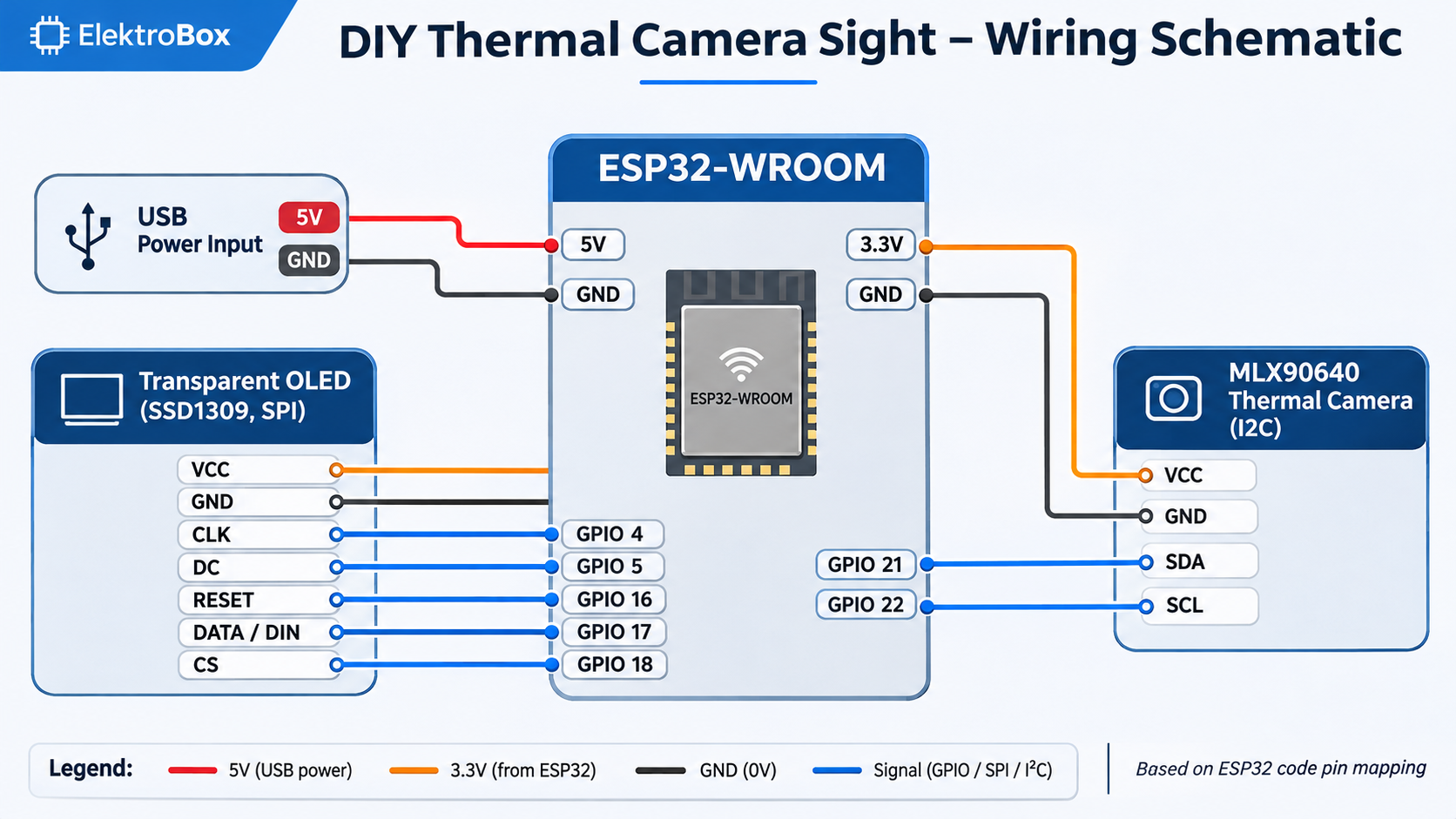
| Module | Signal | ESP32 |
|---|---|---|
| MLX90640 | SDA / SCL | GPIO 21 / 22 |
| SSD1309 | CLK / DIN | GPIO 4 / 17 |
| SSD1309 | CS / DC / RESET | GPIO 18 / 5 / 16 |
| Both modules | VCC / GND | 3.3 V / GND |
Clock labels. SCL is the thermal sensor’s I²C clock. CLK is the OLED’s SPI clock. Verify the salvaged cable by continuity before connecting either module.
Upload the Arduino sketch
In Arduino IDE, select your ESP32-WROOM development board and port. Install U8g2 and Adafruit MLX90640 through Library Manager, then upload the sketch. Open Serial Monitor at 115200 baud to check the background estimate, threshold, and warm-pixel count.
For the bench test, start with an empty view, then move a warm mug toward the center. The OLED shows a large circle when fewer than two pixels meet the threshold. It then uses the qualifying pixel closest to the center to set the circle size. An X appears when that pixel is less than three sensor pixels from the center. The threshold is 3 °C above the smoothed background estimate.
Show the full Arduino sketch
#include <U8g2lib.h> // U8g2 by Oliver
#include <Wire.h>
#include <Adafruit_MLX90640.h>
#include <math.h>

// OLED: rotation, clock, data, CS, DC, reset
U8G2_SSD1309_128X64_NONAME0_F_4W_SW_SPI u8g2(
  U8G2_R0, 4, 17, 18, 5, 16
);

Adafruit_MLX90640 mlx;
#define MLX90640_I2CADDR 0x33

const int sensorWidth = 32;
const int sensorHeight = 24;
const int pixelCount = sensorWidth * sensorHeight;
const int displayWidth = 128;
const int displayHeight = 64;
float frame[pixelCount];

const float temperatureOffset = 3.0;
const int minWarmPixels = 2;
const float backgroundAlpha = 0.2;
float backgroundTemp = 0.0;
bool backgroundInitialized = false;

const int minRadius = 5;
const int maxRadius = 30;
const float centerTolerance = 3.0;

// Estimate the 25th percentile in 0.5 °C bins.
float estimateBackground() {
  const int bins = 241;
  int histogram[bins] = {0};
  int validPixels = 0;

  for (int i = 0; i < pixelCount; i++) {
    float t = frame[i];
    if (!isfinite(t) || t < -20 || t > 100)
      continue;

    int bin = (int)((t + 20.0) * 2.0);
    bin = constrain(bin, 0, bins - 1);
    histogram[bin]++;
    validPixels++;
  }

  if (validPixels == 0)
    return NAN;

  int targetRank = (validPixels - 1) / 4;
  int cumulative = 0;

  for (int i = 0; i < bins; i++) {
    cumulative += histogram[i];
    if (cumulative > targetRank)
      return -20.0 + i * 0.5;
  }

  return NAN;
}

void drawMaxCircle() {
  u8g2.clearBuffer();
  u8g2.drawCircle(displayWidth / 2, displayHeight / 2, maxRadius);
  u8g2.sendBuffer();
}

void drawCenterX() {
  int centerX = displayWidth / 2;
  int centerY = displayHeight / 2;
  int xSize = 5;

  u8g2.clearBuffer();
  u8g2.drawLine(centerX - xSize, centerY - xSize,
                centerX + xSize, centerY + xSize);
  u8g2.drawLine(centerX - xSize, centerY + xSize,
                centerX + xSize, centerY - xSize);
  u8g2.sendBuffer();
}

void drawDistanceCircle(float distance) {
  float centerX = sensorWidth / 2.0;
  float centerY = sensorHeight / 2.0;
  float d_max = sqrt(centerX * centerX + centerY * centerY);

  int radius = minRadius + (int)((maxRadius - minRadius) * (distance / d_max));
  radius = constrain(radius, minRadius, maxRadius);

  u8g2.clearBuffer();
  u8g2.drawCircle(displayWidth / 2, displayHeight / 2, radius);
  u8g2.sendBuffer();
}

void showMessage(const char* message) {
  u8g2.clearBuffer();
  u8g2.setFont(u8g2_font_helvB12_tf);
  int x = (displayWidth - u8g2.getStrWidth(message)) / 2;
  u8g2.drawStr(x, 38, message);
  u8g2.sendBuffer();
}

void setup() {
  Serial.begin(115200);
  pinMode(13, OUTPUT);
  digitalWrite(13, HIGH);
  delay(1000);

  u8g2.begin();
  Wire.setPins(21, 22);
  Wire.begin();

  while (!mlx.begin(MLX90640_I2CADDR, &Wire)) {
    Serial.println("MLX90640 not found!");
    showMessage("NO CAMERA");
    delay(1000);
  }

  Serial.println("MLX90640 found!");
  mlx.setMode(MLX90640_INTERLEAVED);
  mlx.setResolution(MLX90640_ADC_18BIT);
  mlx.setRefreshRate(MLX90640_16_HZ);
  Wire.setClock(1000000);
}

void loop() {
  if (mlx.getFrame(frame) != 0) {
    Serial.println("Frame read error");
    drawMaxCircle();
    delay(62);
    return;
  }

  float measuredBackground = estimateBackground();
  if (!isfinite(measuredBackground)) {
    drawMaxCircle();
    delay(31);
    return;
  }

  if (!backgroundInitialized) {
    backgroundTemp = measuredBackground;
    backgroundInitialized = true;
  } else {
    backgroundTemp =
      (1.0 - backgroundAlpha) * backgroundTemp +
      backgroundAlpha * measuredBackground;
  }

  float threshold = backgroundTemp + temperatureOffset;
  float centerX_sensor = sensorWidth / 2.0;
  float centerY_sensor = sensorHeight / 2.0;

  float bestDistance = 1e9;
  int bestIndex = -1;
  int warmPixelCount = 0;
  float maxTemp = -1000.0;

  for (int i = 0; i < pixelCount; i++) {
    float temp = frame[i];
    if (!isfinite(temp))
      continue;

    if (temp > maxTemp)
      maxTemp = temp;

    if (temp >= threshold) {
      warmPixelCount++;
      int sensorX = i % sensorWidth;
      int sensorY = i / sensorWidth;
      float dx = sensorX - centerX_sensor;
      float dy = sensorY - centerY_sensor;
      float distance = sqrt(dx * dx + dy * dy);

      if (distance < bestDistance) {
        bestDistance = distance;
        bestIndex = i;
      }
    }
  }

  Serial.print("Background: ");
  Serial.print(backgroundTemp);
  Serial.print(" C | Threshold: ");
  Serial.print(threshold);
  Serial.print(" C | Max: ");
  Serial.print(maxTemp);
  Serial.print(" C | Warm pixels: ");
  Serial.print(warmPixelCount);
  Serial.print(" | Center distance: ");
  Serial.println(bestDistance);

  if (bestIndex == -1 || warmPixelCount < minWarmPixels) {
    drawMaxCircle();
    delay(31);
    return;
  }

  if (bestDistance < centerTolerance) {
    drawCenterX();
  } else {
    drawDistanceCircle(bestDistance);
  }

  delay(31);
}