
Five-Channel RGB LED Controller
In this project, I build a five-channel RGB LED controller using two ESP32 boards, PWM output stages, an ILI9341 touchscreen display, and I2C communication between the two controllers.
The controller can drive five separate RGB LED channels. Each RGB channel needs three individual outputs for red, green, and blue, so the final controller uses 15 PWM outputs in total.
1. Required Parts
2. Required Tools
- Soldering iron
- Solder wire
- Wire cutter
- Wire stripper
- Multimeter
- Computer with Arduino IDE
- USB cables for the ESP32 boards
- Optional PCB design software and 3D printer
3. Project Structure
For more complex projects, I like to start with simple subsystem prototypes. This makes the project easier to debug because every function can be tested separately before everything is combined.
4. Test the PWM Color Control
The brightness of each LED color is controlled with PWM. PWM stands for Pulse Width Modulation. The ESP32 switches the output on and off very quickly. By changing the duty cycle, the average power delivered to the LED changes and the LED appears brighter or darker.
For the first prototype, connect one red, one green, and one blue LED to three transistor output stages. In this example, the ESP32 uses GPIO16 for red, GPIO17 for green, and GPIO5 for blue.
PWM test code
5. Output Stage
LED strips need more current than an ESP32 pin can provide. The ESP32 PWM pins should only control the gate or base of the output stage. The LED strip current flows through the external transistor or MOSFET.
For reliable operation, use suitable logic-level MOSFETs and make sure the LED power supply is dimensioned for all channels at full brightness.
Prototype setup with touchscreen control and RGB output testing.
6. Touchscreen Interface
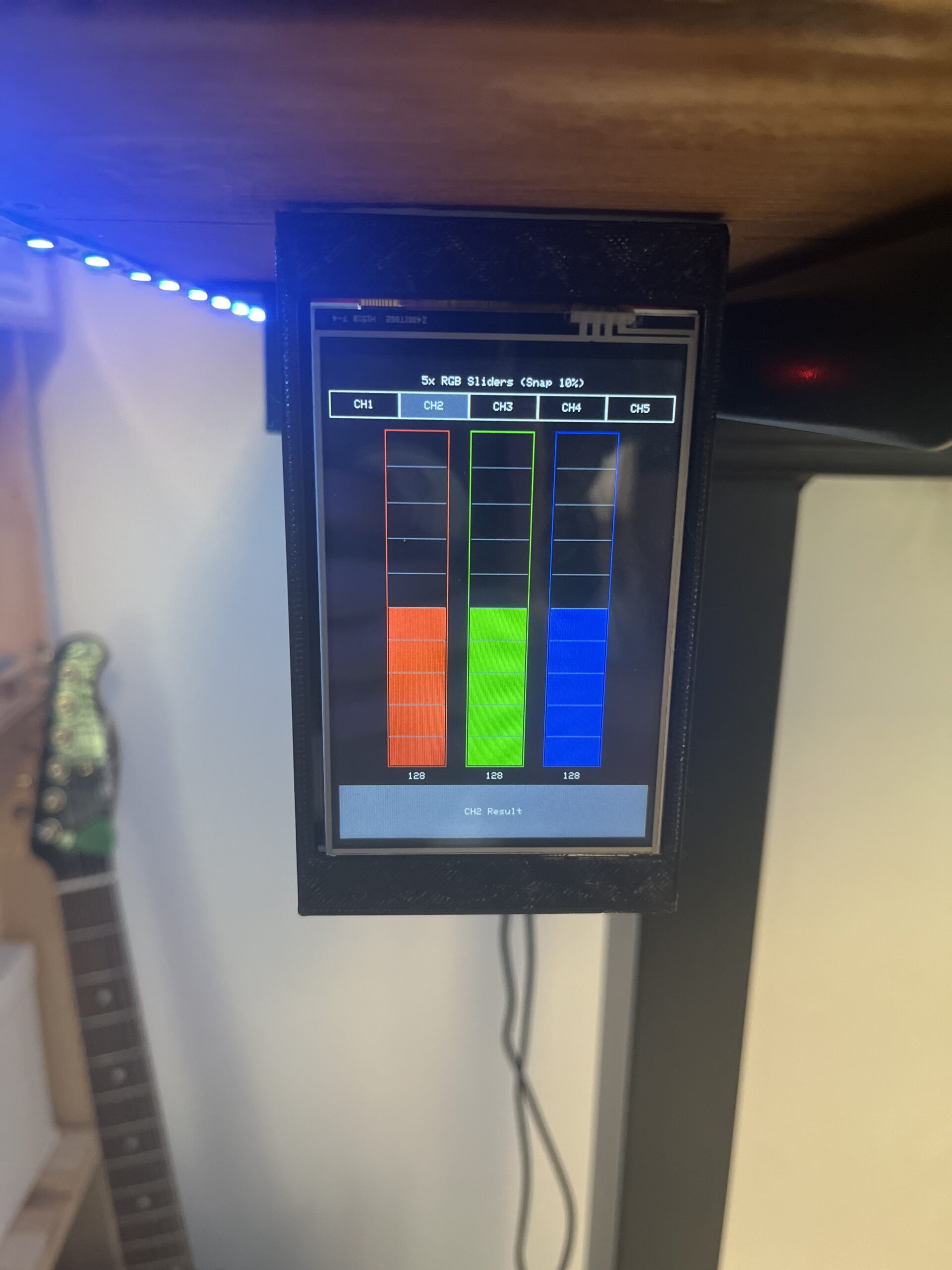
The master ESP32 handles the touchscreen display. It shows the user interface and allows selecting channels, colors, and brightness values.
7. I2C Communication
Because the touchscreen already uses many pins, I split the system into two controllers. The master ESP32 sends the selected channel and RGB values to the slave ESP32 over I2C. The slave ESP32 then updates the PWM outputs.
I2C data concept
A simple message can contain the selected channel number and three color values. For example: channel 3, red 120, green 40, blue 255.
8. Final Software Structure
The final controller uses two separate Arduino sketches. The Master ESP32 runs the touchscreen menu, stores the RGB values for five independent channels, converts the selected color into RGB565, and sends the active channel data to the slave controller over I2C.
The Slave ESP32 listens as an I2C receiver at address 0x42. It receives
three bytes from the master, converts the RGB565 color back into 8-bit red, green, and blue values,
and updates the PWM outputs for the selected RGB LED channel.
LED_Controller_Master.ino
Upload this sketch to the ESP32 connected to the ILI9341 touchscreen. This board is the user interface controller and sends the selected channel color to the slave ESP32.
LED_Controller_Slave.ino
Upload this sketch to the ESP32 connected to the RGB output stages. This board receives the selected color and updates the PWM pins for the five RGB LED channels.
9. Common Problems
The LED strip does not light up
Check the power supply, shared ground, MOSFET wiring, and LED strip polarity.
The colors are swapped
Check the channel order. Some LED strips or wiring layouts use a different RGB order.
The touchscreen works but the LEDs do not react
Check the I2C wiring, addresses, pull-up resistors, and whether both ESP32 boards are powered.
10. Final Result
The final controller uses a touchscreen as the user interface and a second ESP32 for the RGB output channels. This keeps the project modular and makes the wiring easier to understand.
The design can be expanded with saved presets, animations, Wi-Fi control, or a custom PCB for a cleaner final build.