
Piggy Bank Slot Machine
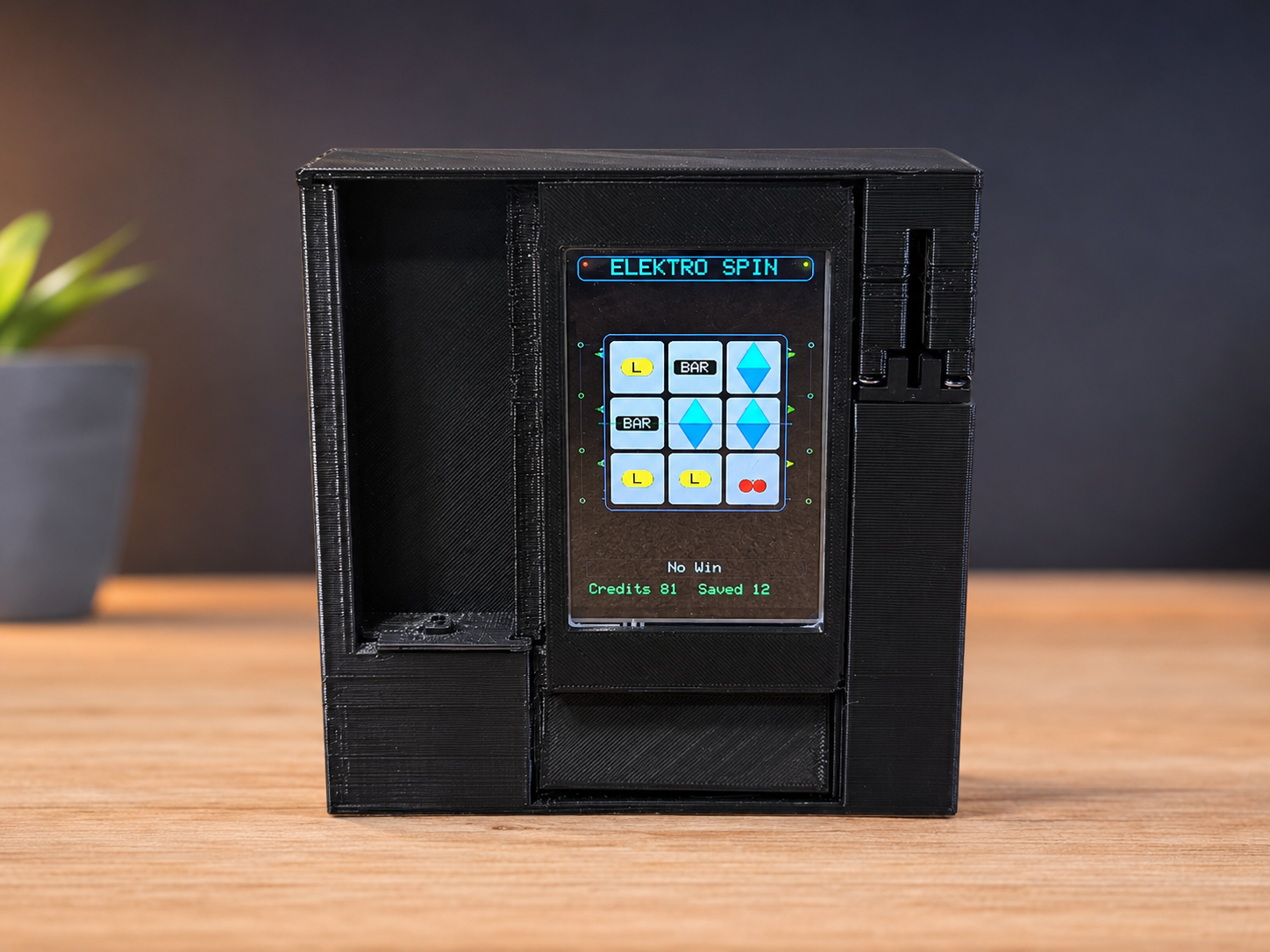
Saving money is usually boring, so I wanted to turn it into a small arcade game. This project combines a piggy bank with a slot machine: every inserted coin gives one spin, small wins give extra spins, and the jackpot unlocks the money chamber.
The machine is built around an ESP32, a coin sensor, a spin button, a TFT display, and a servo-controlled gate. The main idea is simple: coins go in, the game starts, and the chamber only opens when the machine hits 777.
1. Project Idea
The goal of this project was to make saving coins more fun. Instead of just dropping money into a normal piggy bank, every coin gives the player one spin on a small slot machine. The player can win extra spins, but the money chamber stays locked until the jackpot result appears.
2. Required Parts
For the first working prototype, I used the following parts:
3. System Overview
The machine has three main jobs: detect an inserted coin, detect the spin button, and control the gate. The ESP32 connects these parts together and decides when the player is allowed to spin or open the money chamber.
4. Coin Detection with an Optical Sensor
The most important part of the project is the coin detection. I used a TCST2103 optical switch. This component works like a small light gate. One side contains an infrared LED, and the other side contains a phototransistor.
If there is no coin inside the slot, the infrared light reaches the phototransistor. When a coin falls through the slot, it blocks the light. The ESP32 reads this change as the coin signal.
In the prototype code below, the coin input is configured as an active-HIGH signal: the sensor reads LOW when the slot is free and HIGH while the coin blocks the light gate. This matches the uploaded prototype firmware.
| Condition | Sensor state in this prototype | ESP32 interpretation |
|---|---|---|
| No coin in the light gate | LOW / free | No new coin counted |
| Coin blocks the light gate | HIGH / blocked | One coin is accepted and one spin credit is added |
COIN_SENSOR_ACTIVE_STATE in the code or invert the condition in readCoinSensorActive().5. Spin Button
The spin button is wired from an ESP32 input pin to ground. In the firmware, the ESP32 internal pull-up resistor is enabled. That means the pin is normally HIGH. When the button is pressed, the pin is pulled to ground and becomes LOW.
The firmware detects this falling edge and starts the slot machine only if a spin credit is available. A short debounce time prevents one physical button press from being counted multiple times.
6. Servo Gate for the Money Chamber
The housing uses a two-chamber design. One side contains the electronics and the servo. The other side is the money chamber. The servo acts as a small gate that blocks access to the coins.
At startup, the servo is moved into the closed position. When the jackpot condition is reached, the ESP32 moves the servo to the open position for a short time and then closes it again.
7. Slot Machine Logic
The game logic is intentionally simple. Every spin creates three symbols on the display. The middle payline is the main result. If the symbols form a winning combination, the player gets extra spins. Only the jackpot opens the gate.
| Result | Reward | Gate opens? |
|---|---|---|
| 777 | Jackpot | Yes |
| Other strong winning combinations | Extra spin credits | No |
| Small winning combinations | Small number of extra spins | No |
| No win | No extra credits | No |
8. Prototype Electronics Test
Before putting everything into the housing, I tested the electronics on the bench. For the first prototype setup, the ESP32 was mainly used to provide power, read the coin signal, read the button input, drive the display, and control the servo gate.
I also reused my small hardware monitor to directly check whether the coin recognition and button input were working correctly. This made debugging much easier before the full mechanical assembly.
9. Housing and Mechanical Assembly
After the electronics test, I started assembling the full prototype. The housing uses two chambers: the electronics chamber and the money chamber. The coin sensor sits directly below the coin slot, so every inserted coin must pass through the light gate before it drops into the storage area.
For this first version, I soldered the resistors and wires directly to the sensor leads instead of using a separate PCB. This is not the cleanest final solution, but it gives more freedom for cable routing inside a tight 3D printed housing.
Some parts of the 3D print were joined by carefully melting the PLA edges with an old soldering iron. This works for rough prototypes, but it should be done carefully because the visible surfaces can deform easily.
10. Display Rotation Issue
During assembly, I noticed that the display was mounted upside down. Luckily, this was only a software problem. The display output can be rotated by 180 degrees in the firmware, so the hardware did not need to be rebuilt.
11. Final Prototype Result
This is the first working prototype of the piggy bank slot machine. A coin gives one spin, the button starts the slot machine, small wins give extra spins, and the jackpot result 777 opens the money chamber.
The prototype still needs improvements, especially in the housing design, cable management, and gate mechanism. But the basic idea works: the ESP32 can detect coins, manage spin credits, run the slot machine logic, and unlock the chamber only after a jackpot.
In the next version, I want to make the design cleaner, improve the gate mechanism, and build a more arcade-like front panel.
12. Pin Overview
These are the most important pins used in the uploaded prototype code. Change them if your wiring is different.
| Function | ESP32 Pin | Notes |
|---|---|---|
| Coin sensor input | GPIO34 | Input-only pin. The code expects an external signal circuit and active-HIGH coin detection. |
| Constant HIGH output for sensor circuit | GPIO32 | Used as a permanent HIGH signal in the prototype wiring. |
| Spin button | GPIO33 | Uses internal pull-up. Button connects the pin to GND when pressed. |
| Servo signal | GPIO27 | Servo signal only. Use a suitable power supply for the servo. |
| TFT enable / backlight | GPIO17 | Turns the display enable/backlight signal on. |
| Touch CS / IRQ | GPIO26 / GPIO25 | Included for future use, but not used as touch buttons in this prototype. |
Full Prototype Code: piggybank.ino
This is the full Arduino prototype code used for the ESP32 piggy bank slot machine. Create a new Arduino IDE project, paste the code into the main .ino file, install the required libraries, and adjust the pin configuration if your wiring is different.
Code Explanation
Libraries
The code uses TFT_eSPI for the display, XPT2046_Touchscreen for future touch support, and ESP32Servo for controlling the gate servo.
Coin Input
The coin sensor is connected to GPIO34. The code expects the signal to become HIGH when the coin blocks the light gate. An interrupt captures the active edge, while the main loop handles lockout and re-arming so that one coin is not counted twice.
Spin Button
The button is connected to GPIO33 and uses the ESP32 internal pull-up. The firmware detects the falling edge from HIGH to LOW and starts a spin if enough credits are available.
Game State Machine
The firmware uses three main states: idle, spinning, and result. During a spin, the reels update with a short animation. After the reels stop, the code checks the winning condition and updates the credits or opens the servo gate.
Jackpot Gate
The servo starts in the closed position. When the slot machine hits 777, the code moves the servo to the open angle, waits for the configured open time, and then closes the gate again.
13. Next Improvements
The first prototype proves that the concept works. For the next version, the biggest improvements are mechanical and visual rather than electrical.
Final Thoughts
This project is a fun example of combining simple electronics with a mechanical idea. The electronics are not very complicated on their own: one sensor, one button, one display, and one servo. The interesting part is how these pieces work together to create a small interactive machine.
Feel free to recreate this project, change the winning chances, modify the display design, or build a completely different housing. If you build your own version, make sure the money chamber is mechanically safe and that the electronics are powered correctly.