
DIY Time Tracking Monitor
In this ElektroBox project, I build a simple Time Tracking Monitor for gaming breaks, work sessions, or any situation where you want a clear visual timer.
The monitor uses an Arduino Nano, 12 LEDs, resistors, and one setup button. The LEDs work like a progress bar with green, yellow, and red sections, so the remaining time is easy to see at a glance.
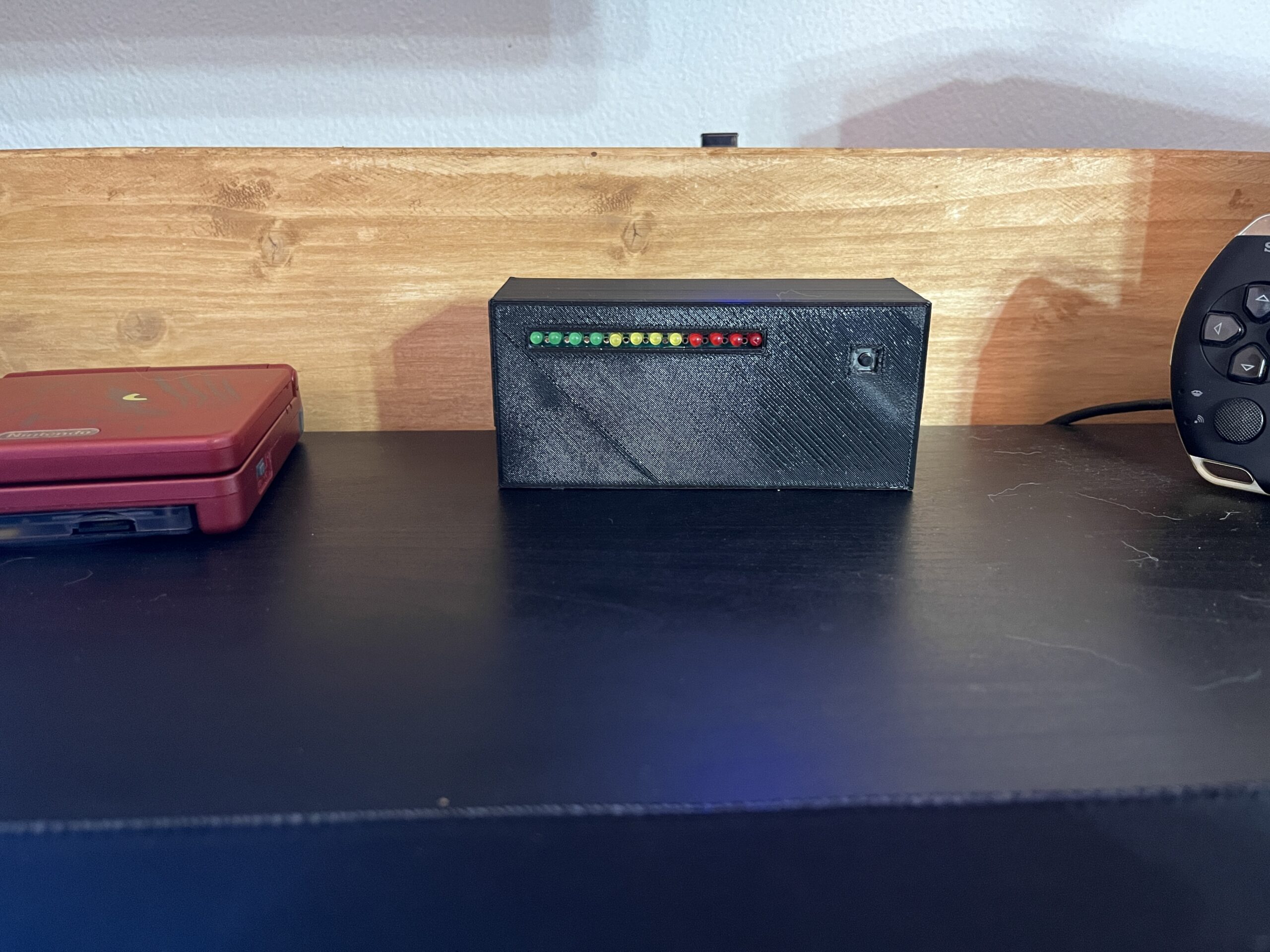
1. Project Idea
In between ElektroBox projects, I like to play games. But sometimes, a short break gets much longer than planned. To solve this, I built a small desktop Time Tracking Monitor.
The idea is simple: before the break starts, the time is set with one button. During operation, the LED bar shows the passed time. When the time is over, a wave animation starts as a visual reminder.
2. How the System Works
The project has four program modes: idle, setup, tracking, and finished. The button is checked continuously, and the Arduino switches between these modes depending on the current state.
Example: If you select 1 hour, the Arduino divides this time across the 12 LEDs. One LED then represents 5 minutes of passed time.
3. Required Parts
- Arduino Nano
- 12 LEDs
- 1 push button
- 12 × 1 kΩ resistors for the LEDs
- 1 × 10 kΩ resistor for the button circuit
- Prototype PCB or perfboard
- Dupont wires
- USB cable for power
- 3D-printed housing
4. LED Status Bar
The LED status bar is built with green, yellow, and red LEDs. I used four LEDs per color to create a simple progress-bar style display.
Each LED is connected from an Arduino digital pin through a 1 kΩ resistor to GND. This limits the LED current to roughly 5 mA, depending on the LED forward voltage.
5. Button Circuit
The setup button is connected to pin A1. In this version, the code expects an external pulldown resistor, so the input is normally LOW. When the button is pressed, A1 is connected to 5 V and reads HIGH.
6. Wiring Overview
- LED 1 to LED 12 are connected to pins D2 to D13.
- The setup button is connected to pin A1.
- The Arduino Nano is powered through USB.
- All LED cathodes are connected to GND.
- Each LED has its own 1 kΩ current-limiting resistor.
Pin overview
7. Program Modes
8. Basic Arduino Code Structure
Timer logic structure
9. Common Problems
One LED does not light up
Check the LED polarity, resistor, solder joint, and assigned Arduino pin.
The button input behaves randomly
Check the pulldown resistor and add debounce handling in the firmware.
The timing is not correct
Use millis-based timing and verify the selected time interval calculation.
10. Final Result
The final result is a compact visual timer with a 12 LED progress bar. It is simple, readable, and useful as a small desktop electronics project.
The project can be expanded with different time presets, a pause function, brightness control, startup animations, or a more advanced button menu.