
DIY LED Matrix Picture Frame
In this ElektroBox project, I build a small LED matrix picture frame using an ESP32 and two chained RGB LED matrix panels.
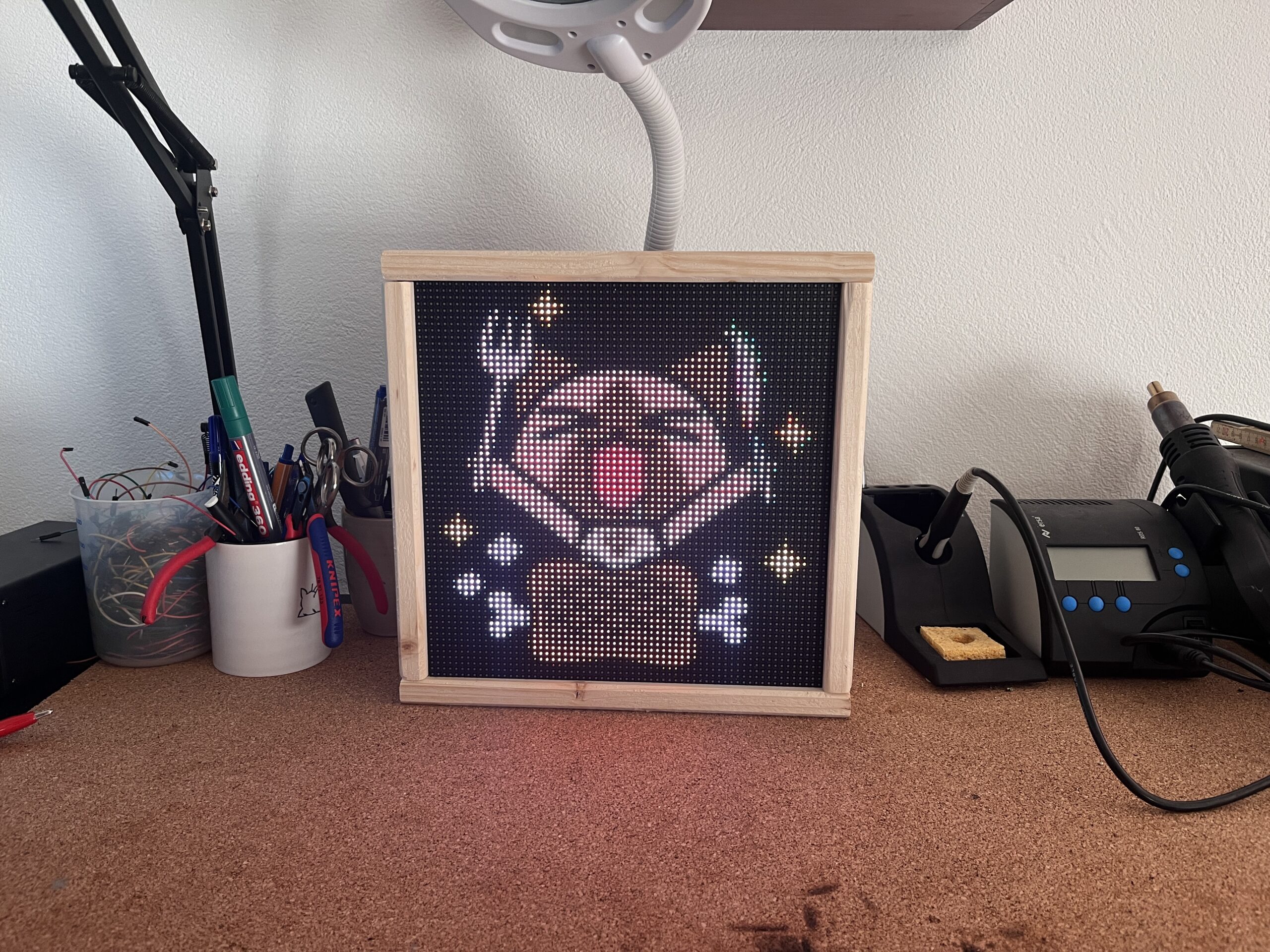
The picture frame displays a custom 64 × 64 pixel image stored as an RGB565 bitmap. The ESP32 reads the bitmap data from program memory and draws it across both matrix panels.
1. Project Idea
The idea for this project came from leftover parts from my ElektroClock build. While working with LED matrix displays, I noticed that multiple panels can be chained together. This makes it possible to create a larger display area and use it as a small pixel-art picture frame.
2. Required Parts
- ESP32 development board
- Two RGB LED matrix panels
- HUB75 ribbon cable or jumper wires
- Stable 5 V power supply
- Leftover PCB from the ElektroClock project or a prototype wiring setup
- Jumper wires
- 3D-printed mounting plate
- Prototype case or enclosure
- Optional screws and spacers
3. How the System Works
The two matrix panels are chained together. The ESP32 controls the input of the first panel, and the display data continues from the first panel to the second one. In the software, both physical panels are handled as one virtual 64 × 64 pixel display.
4. Designing the Mount
To align both LED matrix panels correctly, I designed a simple mounting plate. The plate keeps both displays in the correct position and makes the complete frame more stable.
First, I measured the mounting holes and outer dimensions of the LED matrix panels. Then I designed the back plate and prepared it for 3D printing. The design is kept simple, so it is easy to print and modify for different panel sizes.
5. Connecting the LED Matrix Panels
The LED matrix panels use the HUB75 interface. Several signal wires are required for the RGB channels, row selection, latch, output enable, and clock signal.
In the final version, I reused a leftover PCB from the ElektroClock project. This keeps the wiring cleaner and more reliable. For a first prototype, jumper wires can also be used.
Pin overview
6. Image Conversion
The ESP32 sketch does not load PNG or JPG files directly. The image first has to be resized to
64 × 64 pixels and converted to RGB565. The Python converter below creates two files:
a .h header file for the Arduino sketch and a .bin file for testing or reuse.
Install required Python package
Python image to RGB565 converter
Save this script as image_to_rgb565_converter.py, run it, select your image, and copy the
generated header file into the same folder as your Arduino sketch.
Generated bitmap header structure
The generated header file contains the 4096 RGB565 pixel values. The array name is based on the
image file name. If the generated array is called mhf_64x64, the Arduino sketch must use
the same name.
7. Firmware Structure
The firmware initializes the matrix library, configures the HUB75 pins, creates the virtual 64 × 64 matrix, and draws the generated RGB565 bitmap from program memory.
mhf_64x64.h and the bitmap array is mhf_64x64. If your converter creates a different
name, change both places in the sketch.Complete Arduino sketch
8. Common Problems
The second panel shows wrong colors
Check the RGB pin mapping, scan pattern, panel type, and HUB75 library configuration.
For chained panels, the slower HZ_10M I2S speed and the correct clock phase can improve stability.
The image is mirrored or split incorrectly
Check the virtual matrix chain type and the physical orientation of both matrix panels.
For two 64 × 32 panels stacked vertically, this project uses CHAIN_BOTTOM_LEFT_UP.
The display flickers or resets
Use a stable 5 V power supply, short power wires, and a common ground between the ESP32 and panels. Lowering the brightness can also reduce current peaks and noise problems.
The Arduino sketch does not compile because the bitmap name is missing
Open the generated .h file and check the exact array name after const uint16_t.
Use exactly this name in drawRGB565Image_P(). C++ is case-sensitive.
9. Final Result
The final result is a compact LED matrix picture frame that displays a custom pixel-art image on two chained RGB matrix panels. It is a useful project for reusing leftover display hardware and testing RGB565 image workflows.