
Power Basics For Electronics
Learn how to select and design power systems for electronics projects, including current budget, voltage regulation, grounding, heat, batteries, and protection.
1. What you will learn
2. Power formulas
3. Learning modules
Work through these modules in order. Each module explains one important part of a reliable power system and shows how it affects real electronics projects.
1 Choosing supply voltage Match power rails to the controller, display, LEDs, sensors, and modules.
Every electronics project needs the correct voltage rails. A microcontroller may need 3.3 V, a display may need 5 V, an LED strip may need 5 V or 12 V, and a motor driver may need a separate motor supply. Before connecting anything, check the required voltage of each module.
The most common mistake is assuming that all parts can run from the same voltage. Some modules accept a wide input range because they have an onboard regulator. Others must be powered directly with a specific voltage. Always check the module label, datasheet, or product description before powering it.
- Check logic voltage: A 5 V module is not always safe for a 3.3 V ESP32 input.
- Separate power and logic: Motors, LED strips, and displays may need more current than the controller can provide.
- Do not overload board pins: A GPIO pin is for signals, not for powering large loads.
- Verify polarity: Reversed plus and minus can destroy modules instantly.
Practical example: In an ESP32 display project, the ESP32 may run at 3.3 V logic, while the display backlight or LED strip may need a separate 5 V supply. Both supplies usually need a shared ground so the control signals have the same reference.
2 Current budgeting Add peak loads and keep enough margin in the supply.
A current budget estimates how much current the full project can draw. This is important because a supply that is too weak can cause resets, flickering, unstable sensors, dim LEDs, or overheating regulators.
Do not only add the normal operating current. Also consider peak current. Displays can draw more current at full brightness, Wi-Fi modules can create short current peaks, motors draw high startup current, and LED strips can consume much more current when many LEDs are bright at the same time.
- List every load: Include microcontrollers, sensors, displays, LEDs, relays, motors, fans, and converters.
- Use worst-case values: Estimate current at full brightness, full speed, or during startup.
- Add margin: A supply should not run permanently at its absolute maximum rating.
- Measure real current: After building, confirm the actual current with a bench supply or multimeter.
Practical example: A small LED matrix can draw far more current than the microcontroller. Even if the ESP32 needs only a few hundred milliamps, the display may require several amps at high brightness.
3 Voltage regulators Choose between linear regulators and switching converters based on heat and efficiency.
Voltage regulators convert one voltage into another. A linear regulator is simple and quiet, but it turns the voltage difference into heat. A switching converter, such as a buck converter, is usually more efficient and better for higher currents.
Linear regulators are useful for small currents or low-noise supply rails. However, they can become very hot if the input voltage is much higher than the output voltage. The heat can be estimated with: Pheat = (Vin – Vout) × I.
- Use linear regulators for simple low-current rails: Good for small sensors or clean analog supplies.
- Use buck converters for higher current: Better for displays, LED strips, motors, and battery-powered devices.
- Check dropout voltage: Some regulators need the input voltage to be clearly higher than the output voltage.
- Check heat: If a regulator is too hot to touch, the design needs improvement.
- Add capacitors: Many regulators need input and output capacitors for stable operation.
Practical example: Converting 12 V to 5 V at 1 A with a linear regulator would create about 7 W of heat, which is usually too much without serious cooling. A buck converter is the better choice.
4 Grounding Use a shared ground and avoid routing high-current returns through sensitive signal paths.
Ground is the reference point for your circuit. If two modules exchange signals, they usually need a shared ground. Without a common ground, a signal level may be undefined, even if the signal wire itself is connected correctly.
Ground routing also affects stability. High-current loads such as motors, LED strips, relays, and displays can create voltage drops in ground wires. If sensitive sensor or microcontroller grounds share the same thin return path, the circuit may behave unpredictably.
- Use a common reference: Connect the grounds of communicating modules together.
- Keep high current paths short: Large load currents should not flow through tiny signal ground wires.
- Use thicker wires for power: Power and ground wires must handle the expected current.
- Avoid ground loops in larger systems: Plan where current returns instead of connecting grounds randomly.
- Separate noisy loads: Motors and LED strips should not disturb sensitive analog sensor readings.
Practical example: If an ESP32 controls a MOSFET for an LED strip, the ESP32 ground and LED strip power supply ground must be connected. Otherwise, the MOSFET gate signal may not switch reliably.
5 Power-up checks Verify rails before connecting expensive modules.
Power-up checks help prevent damage during the first test. Before connecting expensive modules, displays, sensors, or microcontrollers, verify that the power rails are correct and that there are no obvious shorts.
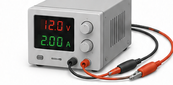
A safe first power-up is controlled and measured. Use a bench supply with a current limit if possible. Start with the current limit set low, switch the circuit on, and watch whether the current rises normally or immediately hits the limit.
- Check continuity first: Look for shorts between power and ground before applying power.
- Measure unloaded rails: Confirm 5 V, 3.3 V, or other rails before connecting sensitive parts.
- Use current limiting: A bench supply can prevent a small mistake from becoming a destroyed board.
- Power in stages: Test the supply, then controller, then display, then external loads.
- Watch for heat: Regulators, ICs, wires, and connectors should not heat up unexpectedly.
Practical example: Before plugging in a display, measure the display connector pins. Confirm that VCC and GND are correct and that the voltage matches the display requirement.
4. Project connections
These examples show where the topic appears in practical ElektroBox builds.
5. Common mistakes
Skipping basic checks
Always verify power, ground, polarity, pin assignment, and the simplest possible test case first.
Changing too many things at once
Change one variable, test again, and document the result. This keeps debugging controlled.
Ignoring component limits
Check voltage, current, heat, pin limits, and power ratings before assuming a circuit is safe.
Final takeaway
Many unstable electronics projects are actually power problems. A good power plan prevents resets, flicker, overheating, and unreliable behavior.