
Practical Electronics Build Skills
Learn the hands-on skills required to turn electronics ideas into reliable physical builds: breadboarding, soldering, wiring, connectors, strain relief, and enclosure planning.
1. What you will learn
2. Build checks
3. Learning modules
Work through these modules in order. Each one teaches a practical build skill that helps turn a quick prototype into a clean, reliable electronics project.
1 Breadboard first Validate the risky or unknown parts of the circuit before soldering.
A breadboard is useful for testing the parts of a circuit that are still uncertain. Before you solder wires or design a PCB, test the sensor, display, button, LED, motor driver, or communication interface separately. This helps you find wiring mistakes and wrong assumptions early.
Do not try to build the full project at once. Start with the smallest working version. For example, if your project uses an ESP32, a button, and a display, first test the ESP32 alone, then the button, then the display, and only then combine everything.
- Start simple: Test one module or function at a time.
- Check power first: Confirm the correct voltage before connecting sensitive parts.
- Use short wires: Long jumper wires can cause unstable signals and loose connections.
- Document working wiring: Take a photo or write down the exact connections before changing anything.
A good breadboard test answers one clear question: “Does this part of the circuit work as expected?” Once the answer is yes, you can move to a more permanent build.
2 Pin planning Create a clear pin table for modules, sensors, buttons, LEDs, and displays.
Pin planning prevents confusion when the project grows. A simple pin table shows which microcontroller pin connects to each module, button, LED, display, or connector. This is especially important when using boards like an Arduino, ESP32, or Raspberry Pi Pico, where some pins may have special functions or limitations.
Create the pin table before soldering. Include the signal name, microcontroller pin, module pin, voltage level, and a short note. This makes debugging much easier later.
- Use clear names: For example BUTTON_START, OLED_SCL, LED_DATA, or FAN_PWM.
- Check voltage levels: Make sure 5 V modules are safe for 3.3 V microcontroller pins.
- Avoid boot-sensitive pins: Some ESP32 pins affect startup and should not be pulled high or low accidentally.
- Reserve programming pins: Keep USB, UART, reset, and boot pins accessible when possible.
A clean pin plan also helps when writing code, because your pin definitions can directly match your wiring documentation.
3 Clean soldering Use enough heat, inspect every joint, and avoid bridges.
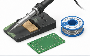
Soldering creates the permanent electrical connections in your project. A good solder joint should look smooth, shiny, and mechanically stable. A bad joint can cause random resets, flickering LEDs, unstable sensors, or complete failure after the project is moved.
Heat both the pad and the component lead, then feed solder into the joint. Do not only melt solder onto the iron tip. The solder should flow onto the heated metal surfaces, not sit on top like a blob.
- Use the right temperature: Around 320–370 °C is typical for many lead-free electronics jobs.
- Keep the tip clean: Wipe and tin the soldering iron regularly.
- Inspect every joint: Look for dull joints, cracks, bridges, or pads without enough solder.
- Use flux when needed: Flux helps solder flow and improves difficult joints.
- Test continuity: After soldering, check important connections with a multimeter.
Common beginner mistakes are using too little heat, moving the wire before the solder cools, applying too much solder, or accidentally bridging two nearby pads.
4 Connectors and cable routing Make the build easier to assemble, maintain, and repair.
Connectors make a project easier to assemble, repair, and modify. Instead of soldering every cable permanently, use connectors for displays, sensors, buttons, power input, LED strips, batteries, and external modules.
Cable routing is just as important as the connector itself. Wires should not be stretched, pinched, sharply bent, or routed across hot components. A clean wiring layout reduces mechanical stress and makes the project easier to understand later.
- Use matching connector types: Choose connectors that fit the current, voltage, size, and number of pins.
- Mark polarity: Clearly label plus, minus, signal, and ground.
- Add strain relief: Prevent cable movement from pulling directly on solder joints.
- Separate power and signals: Keep noisy motor, LED, or power wires away from sensitive signal lines when possible.
- Leave service length: Add enough cable length so the enclosure can be opened without ripping wires out.
A good build should be understandable even after several weeks. Color-coded wires, labels, and consistent connector orientation help a lot.
5 Enclosure preparation Plan mounting holes, cable exit points, ventilation, and access to buttons or ports.
The enclosure should be planned before the final soldering step. Many projects work on the desk but fail when they are installed into a case because connectors are blocked, wires are too short, buttons do not align, or the USB port is no longer accessible.
Place the main components first: display, PCB, battery, buttons, switches, connectors, and mounting screws. Then check the cable paths and make sure the enclosure can still close without pressing on components.
- Check dimensions: Measure the real parts, not only the datasheet drawing.
- Plan access: Keep USB ports, power switches, reset buttons, and charging connectors reachable.
- Use mounting points: Avoid loose PCBs inside the enclosure.
- Protect wires: Use grommets or rounded edges where cables leave the case.
- Consider heat: Add ventilation or spacing for regulators, LEDs, power resistors, and motor drivers.
Before final assembly, do a dry fit without glue or permanent fastening. Confirm that all parts fit, all cables reach, and the device can still be opened for repair.
4. Project connections
These examples show where the topic appears in practical ElektroBox builds.
5. Common mistakes
Skipping basic checks
Always verify power, ground, polarity, pin assignment, and the simplest possible test case first.
Changing too many things at once
Change one variable, test again, and document the result. This keeps debugging controlled.
Ignoring component limits
Check voltage, current, heat, pin limits, and power ratings before assuming a circuit is safe.
Final takeaway
A project is not finished when the circuit works once on a breadboard. Practical build skills turn prototypes into usable devices.