
Electronics Basics
Learn the basic electrical concepts that appear in almost every electronics project: voltage, current, resistance, power, component polarity, simple circuits, and schematic symbols.
1. What you will learn
2. Core formulas
3. Learning modules
Work through these modules in order. Each one is a practical building block for real electronics projects.
1 Voltage, current, and resistance Understand how supply voltage, load resistance, and current flow depend on each other.
Voltage, current, and resistance are the foundation of almost every circuit. Voltage is the electrical pressure that tries to move charge through a circuit. Current is the actual flow of charge. Resistance limits that current and controls how much energy is converted into heat, light, or useful work.
A good way to imagine this is a water system: voltage is similar to water pressure, current is the amount of water flowing, and resistance is a narrow section of pipe that restricts the flow. In electronics, these three values are linked by Ohm’s Law: V = I × R.
- Higher voltage can push more current through the same resistance.
- Higher resistance reduces current when the voltage stays the same.
- Too much current can overheat components, damage LEDs, or destroy microcontroller pins.
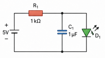
Example: If a 5 V supply is connected to a 1 kΩ resistor, the current is 5 V / 1000 Ω = 0.005 A, or 5 mA. This is a safe current range for many simple LED or signal circuits.
Practical tip: Before powering a circuit, always ask: What voltage is applied? What limits the current? Which component receives the voltage drop? This habit prevents many beginner mistakes.
Self-check: If you double the resistance but keep the same voltage, what happens to the current?
2 Basic components Learn resistors, capacitors, LEDs, diodes, switches, connectors, and simple sensor modules.
Most beginner circuits are built from a small group of basic components. Once you understand what each part does, schematics become much easier to read and projects become easier to debug.
- Resistors limit current, create voltage drops, and define signal levels.
- Capacitors store small amounts of energy and help smooth unstable voltage or filter noise.
- LEDs emit light but must usually be used with a current-limiting resistor.
- Diodes allow current to flow mainly in one direction and are often used for protection.
- Switches open or close a circuit and can be used as user inputs.
- Connectors make it possible to connect power, sensors, displays, and external modules.
- Sensor modules convert physical values like light, temperature, distance, or motion into electrical signals.
Important concept: Some components are non-polarized, meaning they can be connected in either direction. Standard resistors usually do not care about direction. Other components are polarized, meaning direction matters. LEDs, electrolytic capacitors, diodes, and many modules can be damaged if connected backwards.
Example: An LED has an anode and a cathode. The longer leg is often the anode, while the flat side on the LED body usually marks the cathode. If the LED is reversed, it will normally not light up.
Practical tip: When using a new component, check three things first: pinout, voltage rating, and maximum current. These values are usually more important than the component name itself.
Self-check: Which components in your circuit have polarity, and what happens if they are reversed?
3 Series and parallel circuits Understand how component values and current paths change in different circuit connections.
Components can be connected in series, in parallel, or in a combination of both. The connection type changes how voltage, current, and resistance behave in the circuit.
Series connection: Components are connected one after another, so the same current flows through all of them. The total resistance increases because the current has to pass through every component.
- Series resistors add together: Rtotal = R1 + R2 + R3.
- The same current flows through each component.
- The supply voltage is divided between the components.
Parallel connection: Components are connected across the same two points, so each branch receives the same voltage. The current splits between the available paths.
- Parallel branches have the same voltage across them.
- Total current is the sum of the branch currents.
- Total resistance becomes lower than the smallest individual branch resistance.
Example: Two LEDs should usually not share one resistor in parallel, because small differences between LEDs can cause one LED to take more current than the other. A safer solution is one resistor per LED branch.
Practical tip: When debugging, redraw the circuit in your head as current paths. Ask where the current starts, where it can split, and how it returns to ground.
Self-check: In a parallel circuit, do the branches share the same voltage or the same current?
4 Schematic reading Learn how symbols and net labels represent the real wiring of a project.
A schematic is not a physical drawing of the circuit layout. It is a logical map that shows how components are electrically connected. The real parts on a breadboard or PCB may be placed differently, but the electrical connections must match the schematic.
The most important skill is following nets. A net is one electrical connection point that may appear in several places on the schematic. If two points have the same net name, they are connected even when no visible wire is drawn between them.
- Power symbols such as 5V, 3V3, VIN, and GND show supply connections.
- Component symbols represent real parts like resistors, capacitors, LEDs, sensors, and ICs.
- Reference designators such as R1, C3, D2, or U1 identify each component.
- Pin numbers connect the schematic to the real package or module pinout.
- Net labels make large schematics cleaner by replacing long wires with names.
Example: A microcontroller pin labeled GPIO5 may connect to a resistor named R1, then to the anode of an LED. The LED cathode then connects to GND. This tells you the signal path from the microcontroller output to ground.
Practical tip: Start reading from the power input. Find the voltage rails, ground, and then follow one functional block at a time. Do not try to understand the whole schematic at once.
Self-check: Can you identify where power enters the circuit, where ground is connected, and which pin controls each output?
5 First circuit checks Check polarity, resistor values, LED direction, power rails, and common ground before applying power.
Many electronics problems happen before the code even starts running. A simple pre-power checklist can prevent damaged parts, overheating components, unstable behavior, and difficult debugging sessions.
- Check the supply voltage: Make sure every module receives the voltage it is designed for.
- Check polarity: Verify plus, minus, anode, cathode, VIN, VCC, and GND connections.
- Check resistor values: Confirm that current-limiting resistors are installed and have the correct value.
- Check common ground: Modules that exchange signals usually need a shared ground reference.
- Check pin assignments: Compare the physical wiring with the code and schematic.
- Check for shorts: Use a multimeter continuity test between power and ground before powering the circuit.
Example: If an ESP32 sends a signal to a sensor module but both boards do not share GND, the signal may behave randomly because there is no common reference point.
Recommended first power-up: Use a current-limited bench power supply if available. Start with a low current limit, power the circuit, and check whether anything heats up or draws more current than expected.
Practical tip: When a circuit does not work, test the smallest possible version first. For example, blink one LED before adding displays, sensors, buttons, wireless modules, and complex code.
Self-check: Before powering your next circuit, can you explain where current flows from the supply, through the load, and back to ground?
4. Project connections
These examples show where the topic appears in practical ElektroBox builds.
5. Common mistakes
Skipping basic checks
Always verify power, ground, polarity, pin assignment, and the simplest possible test case first.
Changing too many things at once
Change one variable, test again, and document the result. This keeps debugging controlled.
Ignoring component limits
Check voltage, current, heat, pin limits, and power ratings before assuming a circuit is safe.
Final takeaway
Once the basics are clear, every other learning page becomes easier because you can reason about voltage, current, resistance, and power instead of guessing.